
The RobotFreedom robots are controlled by two code bases. The first runs on a RaspberryPi and is written in Python. You can read more about it here. The second code base controls the movements and lights on the robot. It is written in C and runs on a Arduino. This article will get you started on developing with that code base. You can download it GitHub.
Please note, this material is provided for informational purposes only and is not a guide on how to create the designs. Please take a look at our disclaimer.
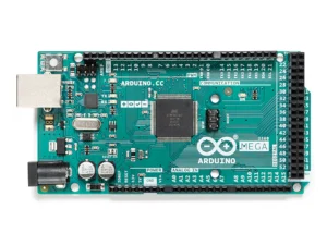
The movement controller is designed to be light and simple compared to the main AI code-base and is ideal for a beginner. The focus is to provide an interface for a human or AI to control a robot’s moving components (arms, legs and wheels). We use a Arduino Mega Board because it has a plenty of digital pin to attach our components to. Below is an image of a Arduino Mega board.
Arduino’s can be controlled via serial communication through a USB port or you can code it to run independently. Our robotic walkers are controlled only by an Arduino. This project is intended to be controlled by an AI installed on a RaspberryPi.
The purpose of the program is to receive incoming messages and perform the requested action. For example ‘a’ means raise the left arm. When the program receives an ‘a’ command it sends a command to a H-Bridge which then send power to a linear actuator to raises the left arm.
To start, install the Arduino IDE on your preferred development OS. Linux, OXS and Windows is supported. You can get the code here.
Next, download the required library and copy them to your development folder.
– Adafruit_BusIO
– Adafruit_I2CDevice
– Adafruit-GFX-Library
– FastLED
Launch the Arduino IDE and from the menu bar select:
Sketch>Include Library>Add Zip Library…
Then point to one of the zip files you have downloaded. Repeat for each required library.
Next select >Sketch>Verify Compile. At the bottom of the IDE a console will appear and provide a detailed log. If you missed any libraries you will receive an error message. Loading any required libraries and try again.
Below is a list of the components the code can control:
– H-Bridge
– FastLED
– Linear Actuator
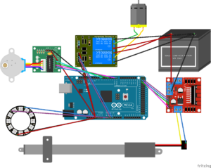
The image below is the wiring for the Arduino:
In the console window type “5”. You should see a response from the Arduino in the console and if the LED is connected to the Arduino it should turn white and flash in a circular pattern.