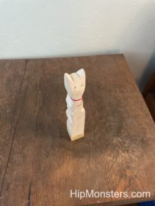
As well as working with technology, the Hip Monsters team also works with magic. This is our handmade apothecary cabinet, which we use to store all of our apothecary supplies and extra bottles.
Please note, this material is provided for informational purposes only and is not a guide on how to create the designs. Please take a look at our disclaimer.
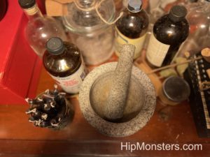
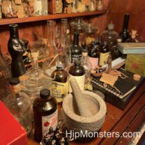
The mortar and pestle is a very useful tool for making potions. It helps us grind up our herbs into smaller pieces to make smoother potions. Grinding up the ingredients will also help release more of the juices and flavors.

Here are some of our bottles. Whenever we get food in interesting jars, we keep the jars to store herbs and potions in. Many of our herbs are from our herb garden, including lavender, roses, and thyme. 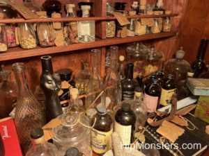
We like to use a variety of different styles of jars to give the collection an organic feel. We also like to store some of our potions in paper packages that releases more of the smell. It also makes the apothecary cabinet look more interesting. 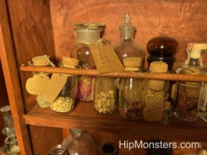
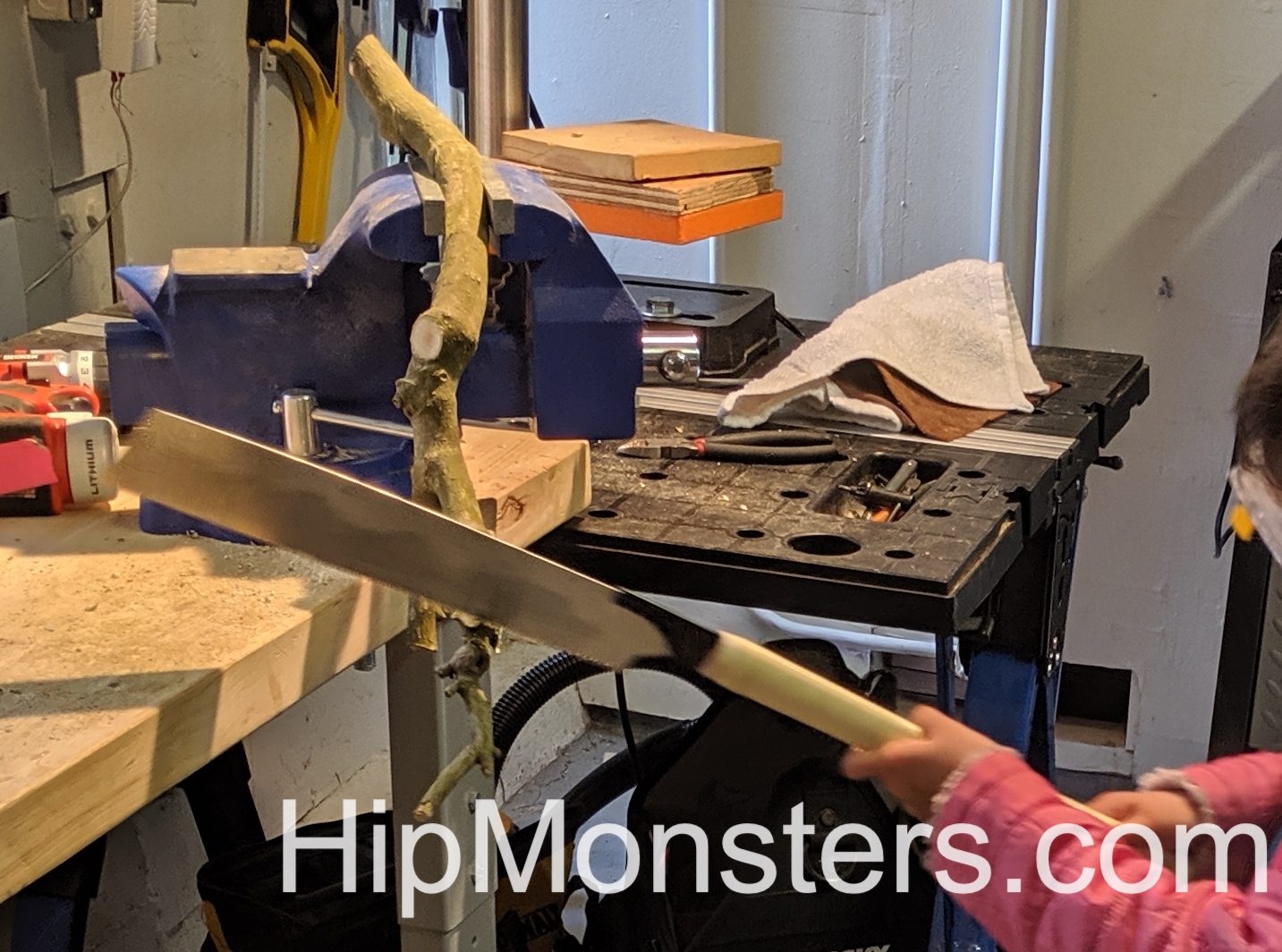
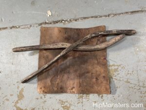
One of the most important additions to our apothecary cabinet was a wooden beam to go across the shelves. This makes sure that the jars won’t fall out very easily.
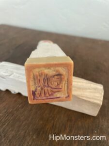
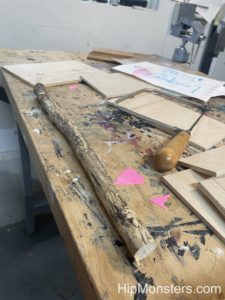
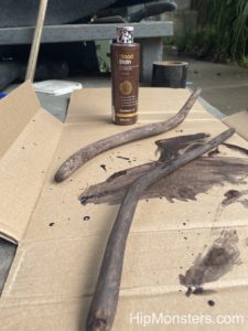
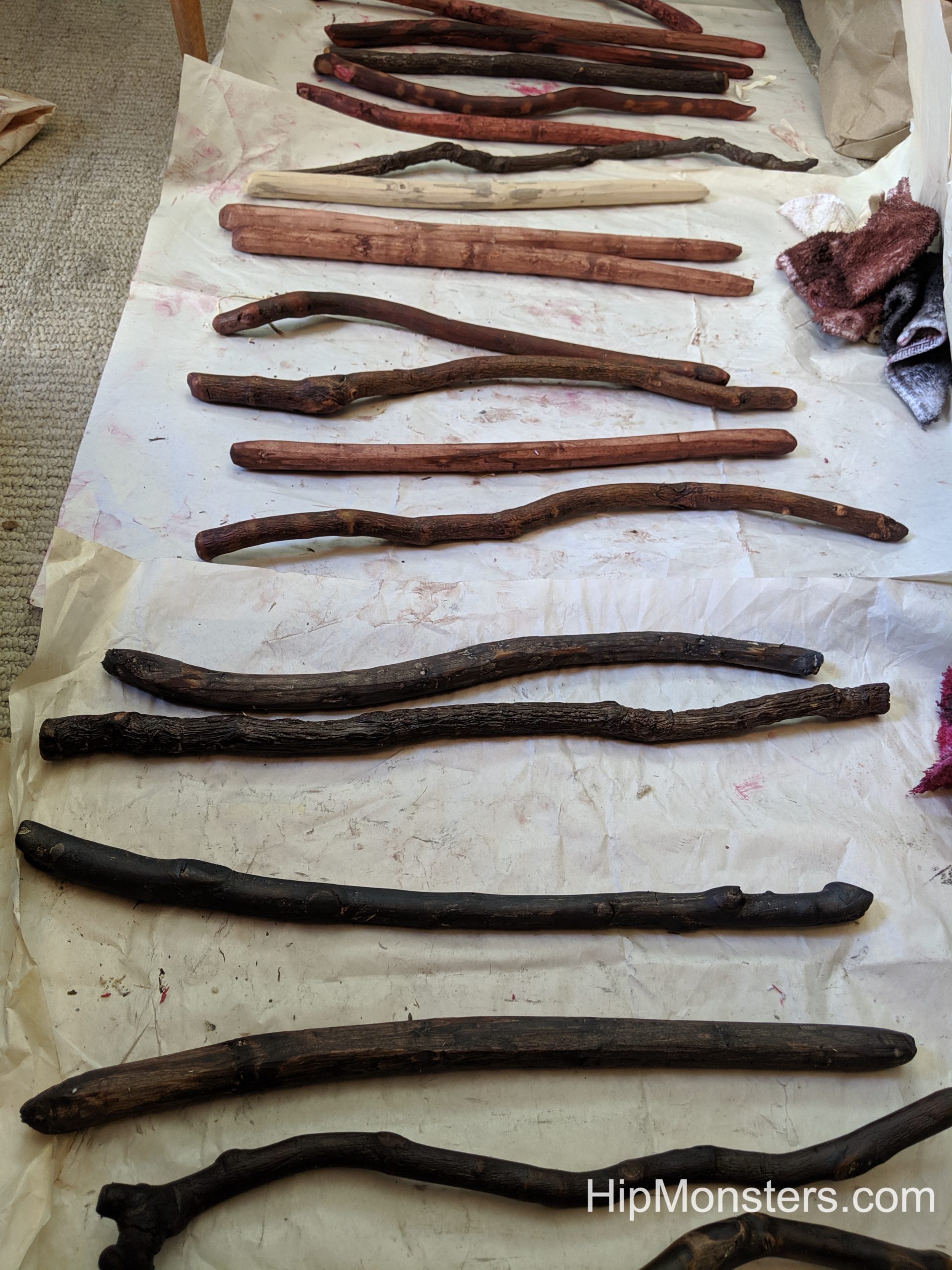
We used three different layers of stain to try and create a older look. After each layer of stain, we would sand the wood before adding the next one. Another technique to make wood look older is to use candle wax to create circles before adding the next layer of stain. The stain will not stick to the wax, which will make it look like there are stains from bottles on the wood.

For labels we used an unbleached present label then cut them to size. This helps us identify all of our different ingredients and also makes the bottles look more interesting.
Happy Creating!


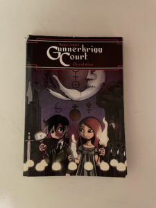


 Inspired by